From previous post, we've known what rendering equation is:
L(x, w) = Le(x, w) + Integral(BRDF(x, w(x, x'))L(x', w(x', x))G(x, x')V(x, x')dA'
x: surface element receiving incoming lights
w: reflection direction
w(x', x): direction from x' to x
G: geometry factor
V: visibility
This is the calculation based on a point on a surface. When producing final image, it actually involves light paths from the light sources to the camera.
Take a look at the (L) inside Integral, this incoming light for point x is also a reflection light for point x', and for point x' itself, it has its own rendering equation. That is to say, if we replace each L inside integral with its rendering equation repeatedly, we will get a multi-integral equation which is called "Measurement contribution function":
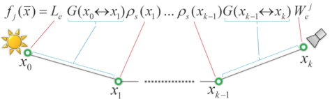
Screenshot from 2013 Siggraph course by Jaroslav Krivanek
the greek letter rho is actually BRDF
In order to solve this multi integral equation, the general approach is using Monte Carlo integration.


the greek letter rho is actually BRDF
In order to solve this multi integral equation, the general approach is using Monte Carlo integration.

Screenshot from 2013 Siggraph course by Jaroslav Krivanek
The main idea of Monte Carlo is utilizing sampling to approximate solutions. For reducing variance, there are many ways to generate samples. here we talk about importance sampling. It is based on probability density function (pdf). Basically, it generates more samples on the region where contributes more to the result, and less samples on the part which doesn't influence the result that much. And because for the region with more samples, the interval of each sample should be smaller, that is why it uses f(x)/p(x) to have proper weight.
Now come back to the light paths integral. With Monte Carlo, we need to know how to properly sample the light path, and what is the probability density of that sampled path to have Monte Carlo estimator ready to be evaluated.
About path sampling, there are different algorithms (ex: path tracing, light tracing, and bidirectional path tracing). Here uses path tracing for instance, the sampling process is based on what is called "local path sampling", which means sample one path vertex at a time. The procedure has three main steps:

Screenshot from 2013 Siggraph course by Jaroslav Krivanek
(1) sample a path vertex from the camera, if using light tracing, sample from the light instead. For camera, usually sample with uniform distribution over the lens surface; for light, sample based on emitted power distribution
(2) shoot a random ray thought image plane to extend the path and get the intersection point
(3) from this intersection point, either sample a direction to shoot another ray based on the BRDF repeatedly until reaching the light source, or test the visibility with the light source and connect them together to form a complete light path
Since local path sampling importance sample the contribution function associated with each path vertex, we can be sure that the path with higher contribution would have more possibility to be sampled.
About the probability density of the sampled path, it's quite straightforward,
p(x) = p(x0, x1, x2, x3) = p(x3)* p(x2|x3) * p(x1|x2) * p(x0)
x stands for the whole path
x3 is camera, x0 is light (assume both are sampled using uniform distribution), x1 and x2 are other path vertices along the way
Simply put, it's the product of conditional pdf of each path vertex.


